The PCB Manufacturing Process Explained
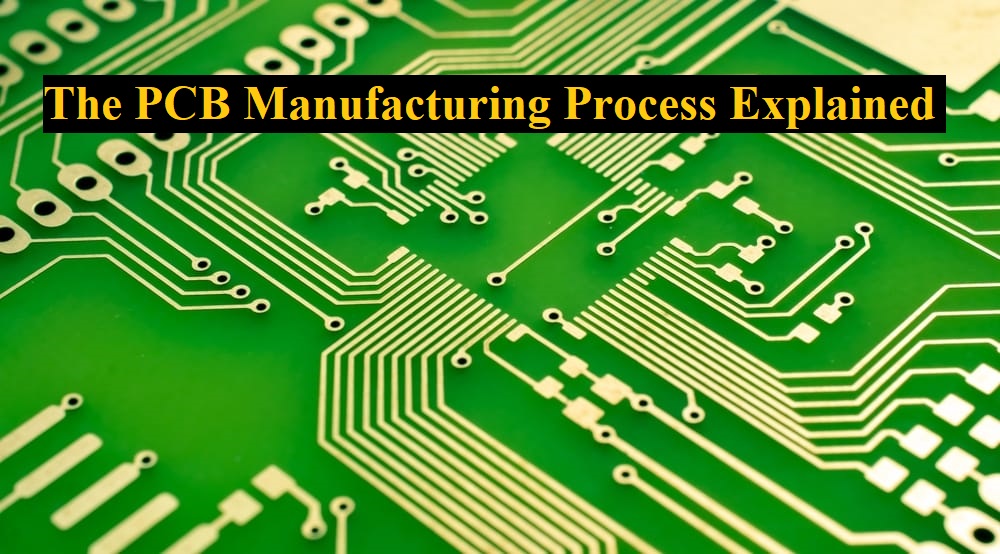
Printed Circuit Boards form an integral part of modern electronics, and PCB production becomes imperative for the reliability assurance of any electronic system, from something as simple as smartphones to complex medical devices. These come in single-sided, double-sided, and multi-layered configurations. The process of printed circuit board manufacturing undergoes many phases through which sophisticated circuits are built to serve as the base for electronic devices.
In this article the aim is to create a step by step guide, so here is the PCB manufacturing process explained…
Designing the PCB
First, it needs to draw a schematic diagram illustrating the components of an electronic circuit and how they are interconnected. There is a defined footprint or an outline associated with each of the electronic components on a circuit that dictates the form of the physical land where a component is placed on the PCB. The components are put on a virtual board, after which the traces—copper connections—can be routed based on how the components interlink as specified by the schematic.
Printing the PCB Design
Unlike conventional designs, none of the PCB plans are printed on a sheet of paper; instead, they are sent to a printer called a plotter to print a “film” that is essentially a photo negative of the board. After the film has been printed, it gets aligned up using a hole called the registration hole, whose purpose is to serve to guide the films later in the process.
Printing the Interior Layers
This is the first step in the whole process where the manufacturer starts to make a PCB. In this step of the procedure, a copper foil layer or copper coating is placed on top of a sheet of laminate material onto which the design of a PCB has been printed. Pre-bonding the copper into the laminate, which is the structural base of the PCB, is conducted. The copper is etched away and the blueprint from before gets revealed. Over the laminate panel, a photosensitive film is deposited. In other words, the photoresist consists of a coating comprising photoreactive compounds that cross-link upon exposure to ultraviolet light. The board is then pressure-washed and left to dry.
Layers or Core are Etched to Expose Copper
The first step before initiating the printed circuit board fabrication process is to strip the core or inner layers of excess copper. The required copper on the board has to be covered, and the rest of it has to be exposed to a chemical that performs the etching. This chemical etching method removes all the unprotected copper from the PCB, leaving only the essential quantity on it.
Layer Alignment
Now that every layer of the PCB has been cleaned, it’s ready for layer alignment and optical inspection. The holes that had been drilled earlier are used in this process of aligning inner and outer layers. The technician uses an optical punch in aligning the layers. The optical punch has a pin that passes through the holes, hence the purpose of aligning the layers of the PCB.
Automated Optical Inspection
Right after layer alignment and an optical punch, it undergoes an optical inspection by the following machine to assure that there are no faults. That automated visual examination comes in very handy because once the layers are assembled, any errors left behind cannot be fixed.
Laminating the PCB Layers
By this point in the process, the PCB layers are all together waiting to be laminated. Once the layers have been confirmed as being defect-free they’re ready to be fused.
Drilling
X-ray equipment is first used to position where the drill sites will be before actual drilling. Registration or guiding holes are then drilled which will hold the stack of the PCB in place before drilling other more specific holes. These are then drilled using a computer-guided drill. Any extra copper is filed off at the edges after the drilling process is complete.
PCB Plating
After the panel has been drilled, it is ready for plating. The plating procedure uses a chemical to fuse all of the PCBs layers together. After being wholly cleansed, the PCB is immersed in a succession of chemicals. Part of the bathing course involves coating the panel in a micron-thick layer of copper. Before being filled with copper, the holes simply expose the fibreglass substrate that makes up the interior of the panel. Bathing the holes in copper coats the walls of the previously drilled holes.
Outer Layer Etching
One of the main differences between the inner and outer layer etching covers the areas that need removal. This ensures non-conductive layers have dark ink covering them and the copper has light ink. Engineers then remove unneeded copper and any remaining resist coating during etching to prepare the outer layer for solder masking.
Solder Mask Application
The panels have to be rigorously cleaned before applying the solder mask. The second step is where an ink epoxy and solder mask coating is applied on the surface of each panel. Exposure to ultraviolet light is done in areas where it marks places where the solder mask will have to be removed. Scrubbing off the solder mask by technicians, before placing the circuit board in an oven to cure the mask is performed. This mask shields the copper of the board from becoming corroded or oxidised.
Surface Finish Printing
Because PCBs need to have information directly on the board, fabricators must print vital data on the surface of the board and should include the following:
- Company ID
- Warning labels
- Manufacturers logo
- Part number
Electrical Reliability Test
After the PCB has been coated a battery of electrical tests are performed on all areas of the PCB to ensure functionality. Electrical testing must adhere to the relevant standards and requirements – one of these tests is the “bed of nails” test. During this test several spring fixtures are attached to the test points on the circuit board. These test points are then subjected to pressure to see how well the PCB stands up and ensure it doesn’t crack or break.
QA Check and Inspection
All PCB’s should go through one final inspection before packaging and shipping. This is to verify:
- Hole sizes match on each layer
- Board dimensions match specifications
- Boards are clean with no dust or debris
- No snags or sharp edges
Packaging and Delivery
The last stage of packaging and delivery is equally as important as manufacture itself. Packaging should be sufficient to keep out dust and other foreign materials, vacuum packing for example before being placed in protective containers that protect them from damage during shipping.
